FPGA Simple UART
Eric Bainville - Apr 2013Serial I/O
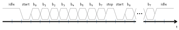
The USB-UART ship is connected to the FPGA using only two signals: RX and TX, for receception and transmission. When no data is transferred, the line is idle and maintained in the high state. To send a bit (assuming 8 data bits, no parity, and 1 stop bit, which is the usual configuration), we first send a '0' start bit, then 8 data bits, and finally a '1' stop bit. Then we are ready to send another byte, or remain idle in the '1' state. This is illustrated in the following diagram.
The main difficulty when designing the UART is to synchronize the reception of bits with the emitter's clock. It may be out of phase with our clock, and the phase may vary over time if the frequencies do not match exactly. To solve this problem, we need a clock running faster than the baud rate, to be able sample the incoming bits at the right time. Here, we take the input clock (the constants given below assume we use the 100 MHz system clock) and generate ticks on sample at 16x the baud rate, i.e. 16 ticks per bit.
entity basic_uart is
  generic (
    DIVISOR: natural  -- DIVISOR = 100,000,000 / (16 x BAUD_RATE)
    -- 2400 -> 2604
    -- 9600 -> 651
    -- 115200 -> 54
    -- 1562500 -> 4
    -- 2083333 -> 3
  );
  port (
    clk: in std_logic;                         -- clock
    reset: in std_logic;                       -- reset
  );
end basic_uart;

architecture Behavioral of basic_uart is

  constant COUNTER_BITS : natural := integer(ceil(log2(real(DIVISOR))));
  signal sample: std_logic; -- 1 clk spike at 16x baud rate
  signal sample_counter: std_logic_vector(COUNTER_BITS-1 downto 0); -- should fit values in 0..DIVISOR-1

begin

  -- sample signal at 16x baud rate, 1 CLK spikes
  sample_process: process (clk,reset) is
  begin
    if reset = '1' then
      sample_counter <= (others => '0');
      sample <= '0';
    elsif rising_edge(clk) then
      if sample_counter = DIVISOR-1 then
        sample <= '1';
        sample_counter <= (others => '0');
      else
        sample <= '0';
        sample_counter <= sample_counter + 1;
      end if;
    end if;
  end process;

end Behavioral;
Next page details the Reception finite state machine.
| FPGA Simple UART : Introduction | Top of Page | FPGA Simple UART : Reception |